Environmental Systems 1 Fall 2014 Duration: 6 Weeks Collaborators: Yiwei He & Julie Bartocci Critics: Ahu Aydogan Akseli, Christian Volkmann
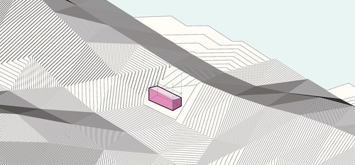
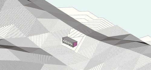
The project brief called for a passive solar residence fora small family in the Knoxville, TN area. Utilizing Sefaira environmental analysis software and various passive solar principles, various designs and forms were investigated until we got to the results you see below.
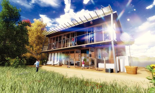
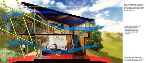
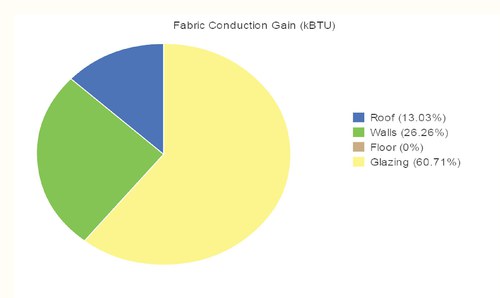
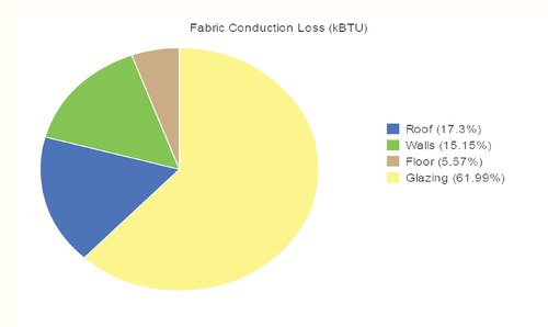
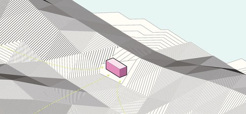
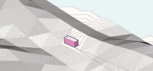
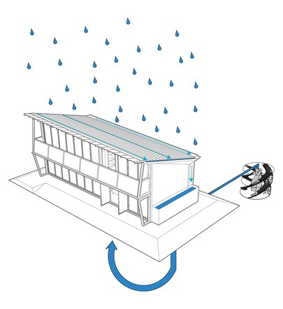
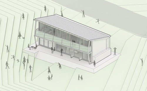
The design of the residence focused on what was called the “three tier” approach. The building envelope is shaped to collect rainwater to be reused as blackwater throughout the structures plumbing systems. The entire form was rotated 10 degrees east of south for optimal solar exposure. The valley site was chosen to take advantage of the cold-air floods in the summer months to passively cool the home. The roof’s overhang and second story balcony control the admittance of direct gain from the southern sun; keeping it out in the summer and allowing it in during the winter. The slab-on-grade foundation of the home acts as a thermal mass, collecting heat during the day in the winter months, and radiating it throughout during the night time. 75% of the facade’s glazing is operable, to maximize cross ventilation from the site’s southerly winds in the summer time. The residence also taps into the Tennessee River to collect water for heating and cooling the home. A water turbine system in the River is connected back to the home and provides energy throughout.
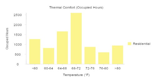
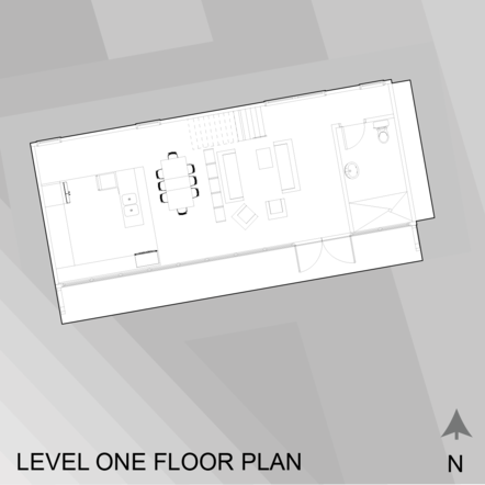
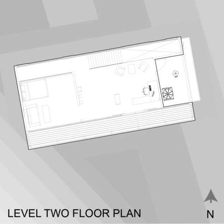
The floor plan is designed as open as much to maximize cross ventilation and fluid air circulation throughout the home. The ground floor features a full bathroom, large kitchen, open dining and living rooms, and an outdoor terrace space on the south side. Upstairs is the master bedroom, a den and office space, and a balcony to the south. The Sefaira results return an 1800 square foot home with good results...48 k/BTU/ft²/yr, heating dominated, and well lit.